But first… I bought an Apple Neo laptop.
Why? I had a perfectly cromulent 17″ Linux laptop running all of my software and development tools etc. I had more than enough screen real estate to do what I needed to do. And yet… this small, portable laptop beckoned to me and I had to buy it. First, the price was right. Second, the 17″ beast takes a toll on my shoulder just lugging it around. It’s a beefy bit of kit and I didn’t always need all of that screen space. Third, interfacing with my other Apple communications channels, such as email and texting, didn’t work in the Linux environment. True, I had my iPad to do all of that, but that meant that I had two systems doing the work of one. So I sold my Linux laptop for about the price of the Neo and I gave Claire my iPad. As I also had a portable 15″ LCD display that I could plug into the laptop when needed, it made sense to switch.
The Gemification of Old Code
Like all technology, it’s great when it’s working, until it doesn’t.
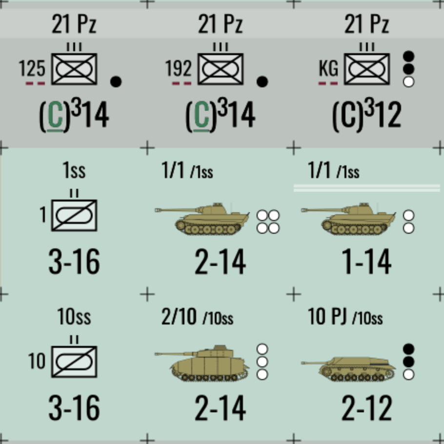
I’ve been working on the Killing Ground reprint in the background for about three years now, give or take a year. And like all projects, its intermittent nature has not made its progress or management any easier.
To whit: I created new counters. However, since some of my code was under a murky Brick Mill Games copyright conflict, or could be interpreted as such, I built the new counters by rewriting old ideas in a new way to avoid such a conflict. To complicate things even more so, I wrote the second version as discrete logic, not as a Gem library.
With Brick Mill Games, LLC’s official passing as of a week or so ago, and with the copyright situation settled, I set about converting the Killing Ground development code into a KGX gem. This gem, and an associated Rakefile, can now be used to build the updated counters. But the effort exposed some underlying technical debt and a second new gem needed to be written.
Chit-Engine is a Ruby gem which standardizes the various wargame support code that I’ve been working on for over a decade now. With its roots in the code I wrote to support the development of Jaws of Victory, and honed during MASL/TOCS development, chit-engine now serves as a general-purpose wargame counter and countersheet generation tool. Not only does it support the creation of individual graphics as well as wholesale countersheets, complete with a virtual die for sheet layout, but external countersheet graphics can be virtually sliced into individual graphics elements.
While KGX relies on chit-engine, both rely on PixMill, my interface to the Cairo and Pango code libraries, a Ruby gem that I thought was mature enough to just use and forget about. I thought that version 1.5.0 was going to be the primary version for months to come. That is, until about four days ago.
Standards, Schmandards
It started with an observation. I was looking into the internals of some SVG graphics and realized that I really hadn’t followed the spec when I wrote my path descriptor logic within PixMill. I won’t bore you with a full technical description of the issue. Here’s an example instead:
<path d="M0,0 a20,20 0 0,1 0,40 a20,20 0 0,1 0,-40 z" /> <!-- Draw a circle by drawing two half circles -->

<path d="M 0 0 a20 20 0 0 1 0 40 20 20 0 0 1 0 -40 z" /> <!-- Same thing -->
First, the commonalities: both circles are drawn at coordinate 0,0, and are 20 pixels in radius. The circles are drawn by moving the virtual pen to 0,0 and drawing a half circle clock-wise until you get to an offset 40 pixels down (radius is 20 pixels, a full half-circle would be 40 pixels down), then it draws another half circle 40 pixels up. The ‘z’ command closes the path even though you’re back where you started at 0,0.
The first descriptor command shows the activity as move (‘M’), arc (‘a’) and another arc (‘a’). The second descriptor shows the two arcs as two sets of data attached to a single arc command. Also, some of the data in the first descriptor is separated by commas while the data elements in the second descriptor is all separated by spaces.
A misreading of the SVG spec on my part made my path descriptor parser too strict. My code only allowed for single sets of command parameters and did not account for spaces being used where I expected commas.
More Loose Threads
Rewriting the parser to be more lenient and intelligent was a more intrusive change that I originally thought it would be. Once I got the basic tokenization figured out, I then had to go into each command processor and allow it to loop through multiple data sets for each command element. That resulted in version 1.5.1.
After visiting quite a few bits of code in the path logic that I hadn’t touched in a while, I got a bad case of refactoritis. The post-tokenization logic to draw the path used this strange array copy, destructive shift method to process the data. Why not use indices into the source array instead of doing this build-up / tear-down thing for every path? In researching this, I also found a bug introduced in 1.5.1. And so, version 1.5.2 was born.
Version 1.5.3 was born out of a desire to simplify path descriptors. I did some research, which I’d done in the past, regarding path descriptors for circles. As in the example above, why can’t I just draw a full circle in one ‘arc’ command using one set of data elements? The answer: there are infinite circles that can be drawn if you only specify the end point as the starting point without any extra data. Drawing a circle as two half-circles is common in SVG world and somewhat trivial. Somewhat. I bet I could make it easier…
The SVG path specification is great at building segments of a path. Building complete shapes, like circles and rectangles, is not a built-in thing. So I made it one. 1.5.3 contains “extension” support. My path descriptor parser now supports two-character extensions commands, where the first character is an ‘X’ or ‘x’, for absolute or relative extension placement, and a ‘c’, or ‘r’, for circle or rectangle. Complete shapes can be specified in this way. Now, I can specify a circle, such as the one in the example above, as “Xc20,0 20 1”: draw a circle centered at 20,0 with a radius of 20 and draw it in a clockwise direction. The ‘Xr’ extension works in a similar manner, and it includes a corner radius value to support rounded rectangles. What’s nice about this is that I can define new extensions in the future, such as “hexagons”, as well as use these shapes as complete sub-paths in more complex descriptions.
I have to thank my new laptop for leading me to version 1.5.4. Because I hadn’t configured Git/LFS correctly, the image files in my test area were not actual images but textual information. Running PixMill tests on the Neo resulted in hard crashes. After I got over my “buyer’s panic”, I discovered that the issue was in how I was handling errors in the Cairo layer. If the Cairo library hits an error when loading a PNG file, it creates a “null” surface. As I was only checking for the existence of a surface, the error was undetected. It turned out that I need to call a status function as well. So I fixed the library and reconfigured LFS. No more errors.
Was I Done? Nope.
“Being a software engineer suits you perfectly because you never finish any of your projects.” – Michael Guerin, Brother, circa 1990s
I know what I want to do and how I want to do it. If the software doesn’t allow for such things, change it if you can.
One of the features that I coded into my PixMill library is the ability to use “scaling coordinates” and to use objects not only as objects to be drawn but objects as layout devices. For example:
gs.set(layout: :xy, posx: 0, posy: 0)
square = Rectangle.new(parent: viewport, w: 250, h: 250, gs: gs)

gs.set(posx: 50, posy: 50, fill: :red)
Circle.new(parent: square, r: 25, scale: 100).draw(gs)
The code above will create a square at 0,0 of size 250 pixels. A red circle with then be drawn within the square. There is an interesting difference between the coordinate systems used. The square uses absolute coordinates and sizes: 250 pixels at 0,0. The circle, however, has specified a scale of 100. This value means that the circle will be positioned and sized using percentage units. So the posx and posy values set do not specify a 50,50 coordinate but a 50%,50% coordinate. In other words, the circle will be centered in the square. The radius is also given as 25, but it’s 25% of the size of the square, not 25 pixels.
This construct is very useful in building graphics elements that can scale with size changes. For example, when I’m creating counters for wargames, I use this to define areas on the counter in percentage points and align/center items within those locations. And it’s scalable and will do the right thing if it’s a 1/2″ or a 9/16″ counter.
However, what if the square wasn’t a square, but a rectangle? What would happen? You would get an ellipse. The percentage scaling applies to each axis separately, meaning that the horizontal and vertical radii would be different. So you’d get an ellipse even though the object you wanted was a circle.
How can we get around this? How can we force a circle, or a square, when we have anisotropic scaling in effect? One way would be the following:
gs.set(layout: :xy, posx: 0, posy: 0)
rect = Rectangle.new(parent: viewport, w: 500, h: 250, gs: gs)
bbox = rect.bbox
gs.set(layout: :gravity, gravity: :center)
square = Rectangle.new(parent: rect, w: bbox.h, h: bbox.h, gs: gs)
gs.set(posx: 50, posy: 50, fill: :red)
Circle.new(parent: square, r: 25, scale: 100).draw(gs)
This method creates a square which is as big as the height of the rectangle and centers it within the parent rectangle. Then the circle is drawn within the centralized square. It works. It’s also cumbersome.
The following does the same thing:
gs.set(layout: :xy, posx: 0, posy: 0)
rect = Rectangle.new(parent: viewport, w: 500, h: 250, gs: gs)
gs.set(posx: 50, posy: 50, fill: :red)
Circle.new(parent: square, r: 25, scale: 100, bias: :shorter).draw(gs)
The bias argument was added to allow for sizing arguments to be scaled based on only one of the two axes of the enclosing object. So, in the code above, the radius would be 25% of the shorter of the parent object’s width and height. Note that this code would work the same if the rectangle were taller instead of wider.
Version 1.5.6 expanded the concept to paths where descriptors included relative movement of the pen. This allowed for the circle extension descriptor to behave the same as the Circles given in the examples above. Anyone who knows the NATO symbol for artillery would understand why I had a keen interest in pursuing this functionality.
Are We There Yet? CCMF!
“Choo-choo, motherf…!”
With all of the changes to PixMill, I had to run my Steel & Steam code through its paces as it also uses that library. And … it all worked well, until I saw logos and the copyright strings for the maps either missing or in the wrong places.

Motherf…..
Version 1.5.7 and 1.5.8 became fixes for the interface between my GraphicsState construct and Cairo’s drawing context. It’s too technical for a full explanation. Suffice it to say that my idea of how it was supposed to work and how it did work were not the same. The design was faulty. Years-old comments near the code in question even asked, “Is this solving a real problem?” The answer was No and it hid other questionable code that masked some fundamental defects.
Finally, 1.5.9 added some long-delayed functionality regarding user coordinate system support. Steel & Steam graphics code does a lot of work converting inches to pixels and does this on every coordinate and size parameter passed to PixMill. If only PixMill supported user coordinate systems outside of its scaling method.
And so, a new parameter was born: uum, or user unit multiplier.
Say you’ve created an image that is 2550×3300 pixels, or 8.5×11″ @ 300dpi (“dots per inch”). Let’s say that you want to paint a 1″ square whose bottom right corner is 1/2″ from the bottom right corner of the full graphic. You could do the math yourself:
gs.set(layout: :xy, posx: 2100, posy: 2850)
Rectangle.new(parent: viewport, w: 300, h: 300).draw(gs)
This works because we did all of the math ourselves. The 1″ square would be 300 pixels in size at 300dpi and the top-left corner would be at 7″x9.5″ or 2100,2850 at 300dpi. Works a treat. Of course, if you want to change it to support 600dpi, you’re screwed b/c you would have to change the code to something like this:
gs.set(layout: :xy, posx: 4200, posy: 5700)
Rectangle.new(parent: viewport, w: 600, h: 600).draw(gs)
Now, this example is trivial. Changing the parameters for one graphic is trivial. Changing it for an entire map is much less so. However, using uum we can do the following:
DPI = 300
gs.set(layout: :xy, posx: 7, posy: 9.5)
Rectangle.new(parent: viewport, w: 1, h: 1, uum: DPI).draw(gs)
Now we have code which supports a coordinate system based on inches and the output quality for the entire graphic can be set by changing one constant. For small graphics, you probably won’t do this, but for large graphics, like a game map, it can make a lot of the code easier to write and support, especially if you need to change the image quality of the graphic.
All Done For Now
And so, PixMill, Chit-Engine and KGX are in a good solid state. It’s time to switch to Steel & Steam and get its components ready for resume playtesting this year as well as modernize the TOCS code for future work.
As always, stay tuned…